
Train Watchr #
Project Description #
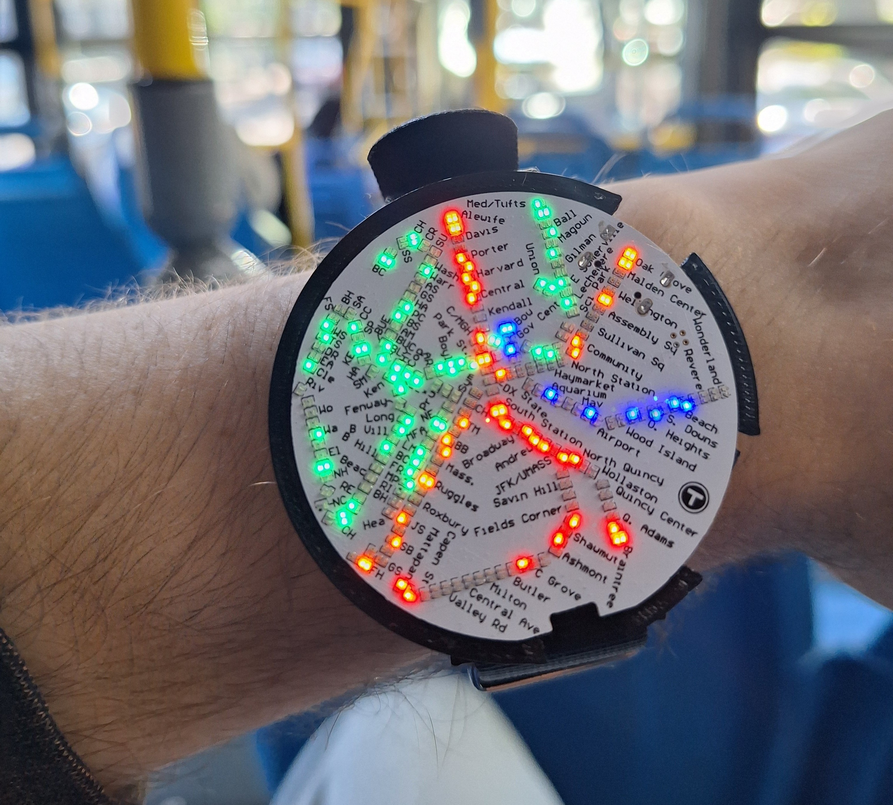
This project set out to make a watch capable of displaying the locations of MBTA trains in realtime. The watch connects to a phone over bluetooth, and a custom app pulls the location of the trains from the MBTA API. I designed the hardware/firmware, and Jeff Asamoah designed the app. The project is inspired by the traintrackr project.
Project Backstory #
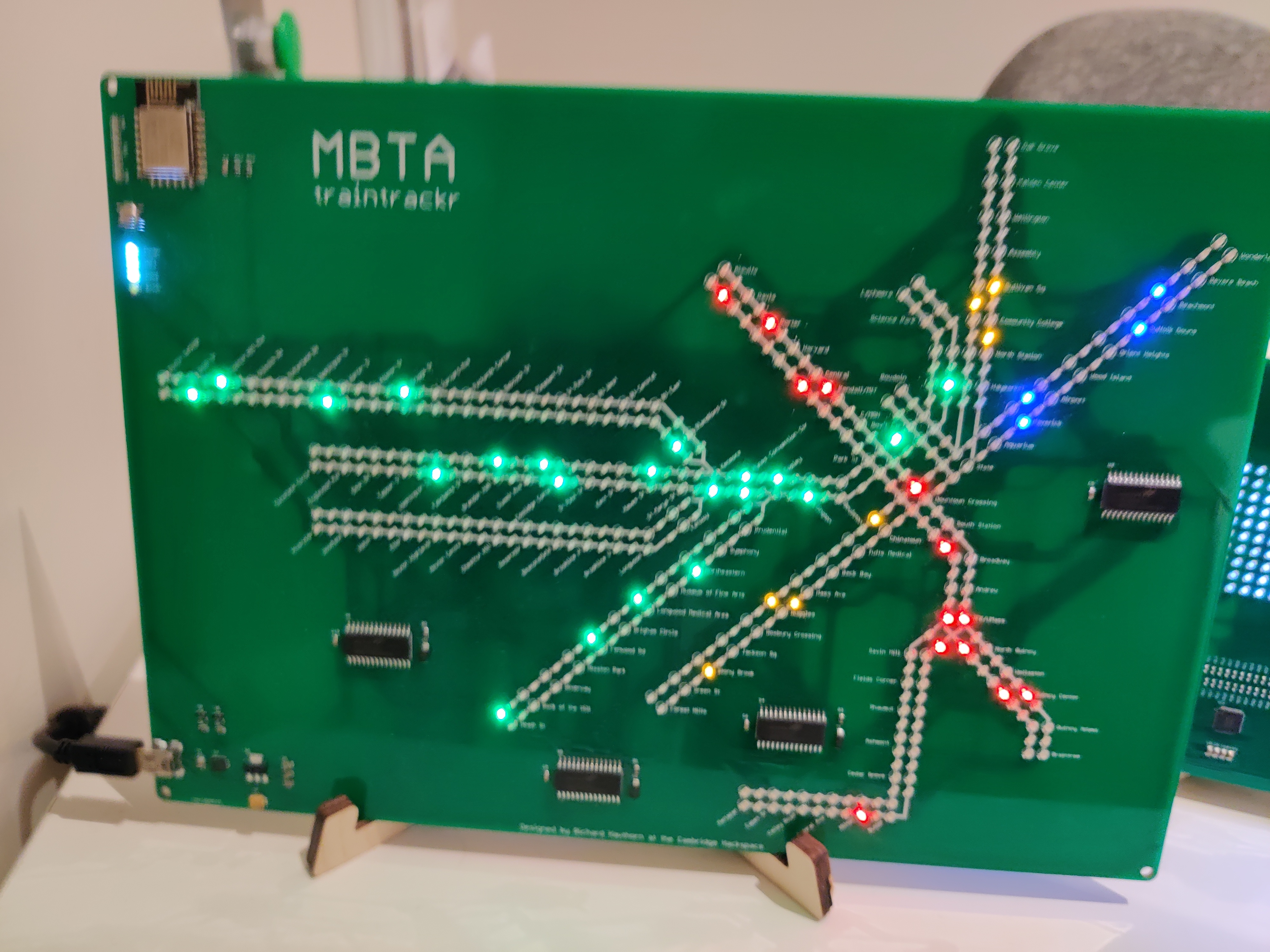
When I moved to Boston one of the first things I did was visit Boston Public Library (BPL). In the corner of the library is the map room, which contains many maps of Boston throughout its history. It’s a very interesting exhibit, especially considering how much of Boston has been built on landfill. However, in the corner of the room there was a map from the future. It was called traintrackr, and it displayed the real time locations of all the trains in the MBTA (Boston’s subway). It was very striking. I thought it would be cool to shrink it down to a watch. I took a picture to remember it for later, and thus began my journey to miniaturize
I convinced a friend of mine not in Boston (thank you Jeff for agreeing to this!). I focused on the hardware, Jeff focused on the software, and we met in the middle to work on the firmware.
What I learned #
This section is meant to detail different things I learned/think are valuable from my perspective working on the project.
LED Display #
The main hardware challenge faced during this project was the challenge of miniaturization. Past LED projects I have done used addressable LEDs. These are great for larger scale projects. They work by including a small integrated circuit (IC) near each LED that controls the color and brightness. The IC also can send and receive data allowing all LEDs to be controlled digitally by passing information into a shift register. In the quest of miniaturization, There is not enough room for each LED to have a dedicated chip next to/inside of it. For this project I used different color 0201 LEDs for each line matching the colors of the MBTA.
To drive each of those LEDs, I set up an LED matrix.
A quick summary of an LED matrix is that the LEDs are wired up such that each anode/cathode has a corresponding row/column of wire. By “turning on” the row and column corresponding to a specific LED you can selectively turn on that LED (turning on is in quotes since you’re really applying a potential difference across the LEDs). Then, by multiplexing the LEDs, you can make the display appear as though all of the LEDs required for your image are on simultaneously. To see this effect in the real world, try recording any LED matrix or seven segment display with the slow motion setting of your phone. You should be able to see the lights cycle as the device turns them on and off.
My initial implementation approach was to use a large I/O expander with the intention to write a firmware driver to handle all of the LED matrix logic. This approach was abandoned for two reasons. First, the IO expanders I was using were a bit big. My first attempt at routing was not manufacturable. This was because I violated hole to copper clearance. I was not aware of this clearance constraint previously, and so every single via (over 1000) was violating this rule. I felt the only way to make everything fit was to start over and attempt a more intelligent wiring scheme. Second, using a dedicated driver would significantly lighten the firmware load while also adding more functionality.
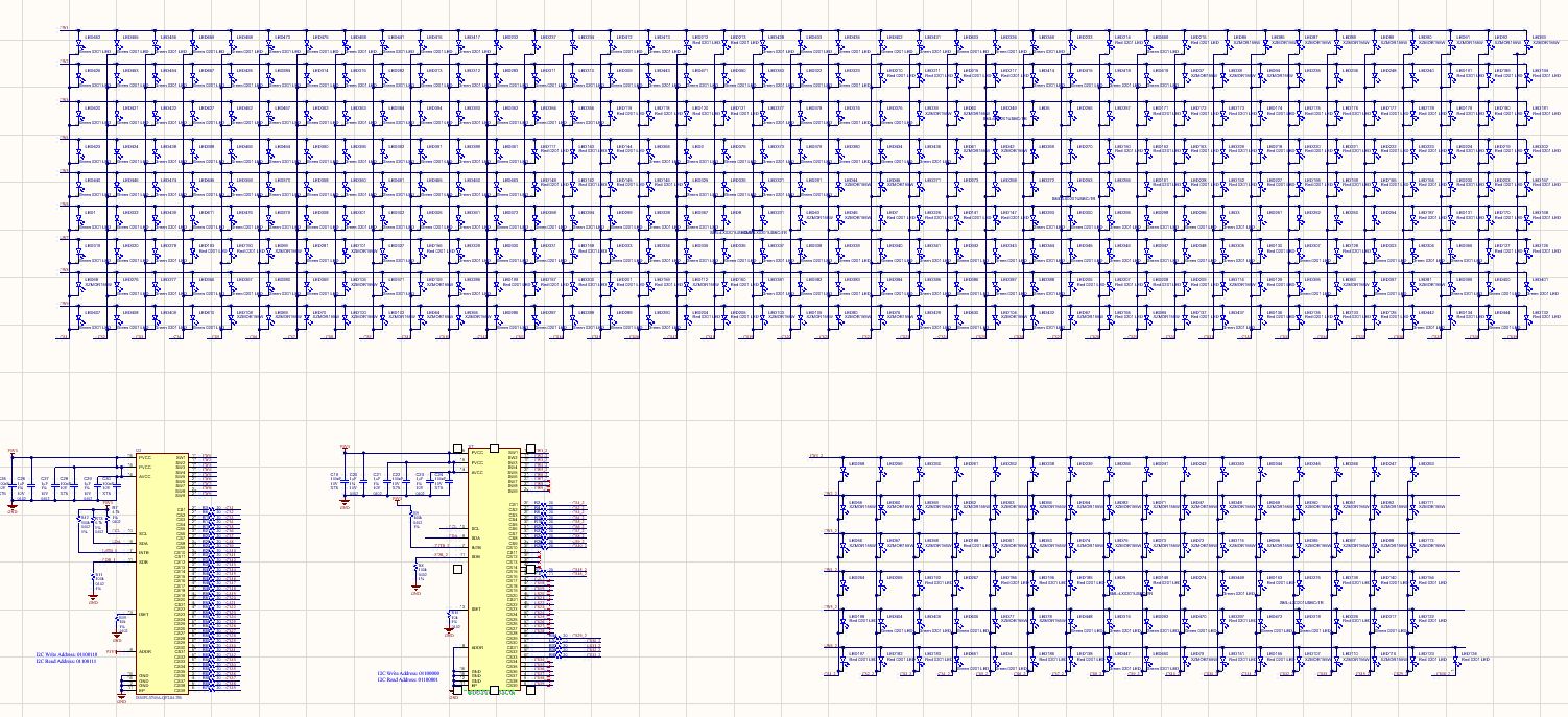
The driver I used was the IS31FL3741A from Lumissil. I love this chip. It made it very easy to control a 39 x 9 LED matrix. As you can see in the schematic image above, I used two of these to drive all of the LEDs required by the system. I cannot stress how easy this chip made my life, and highly recommend it. The main drawback to using this was availability/bill of materials (BoM) cost. JLCPCB requires you to order all of your parts ahead of time. If the parts are not in their (admittedly large) catalog, you must order them to the factory. This can take 5-30 business days and delay the order. Normally I wouldn’t mind, but since I ordered these in April 2025, the tarriffs on chinese goods was climbing daily while I could do nothing but watch. Ordering from a domestic supplier still was more expensive, given that I needed the factory to do assembly as well.
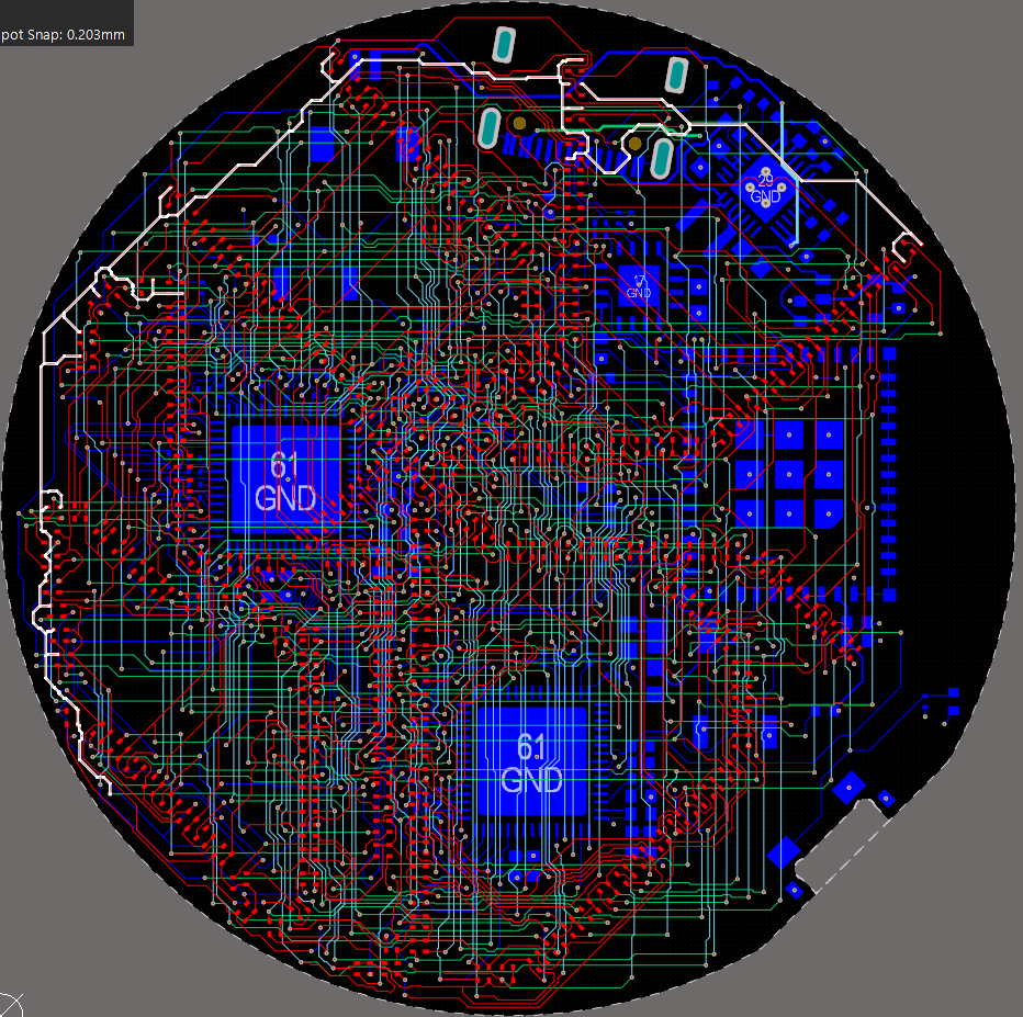
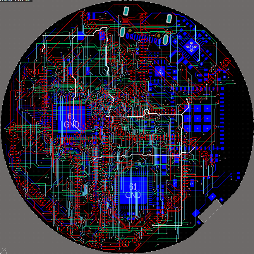
As much as I loved this chip, it also created the biggest pain point of the project: mapping an LED matrix to a transit map. Astute readers may have noticed that the MBTA is not laid out in a perfect grid. This meant a lot of meandering traces. While I initially tried to string the rows together in somewhat of an orderly fashion, the columns were a bit more difficult to work with. I spent a lot of time with the component swap tool, which let me swap the position of two LEDs in the layout. Below you can see an example of how the traces were drawn after the dust settled.
ESP32 Mistakes #
I had chosen the the ESP32 since it is commonly used by the larger maker community. I overlooked a few things, which I’d like to share as a warning for any other potential users I would consider these all dumb mistakes that could have been checked with more due diligence. But some things must be learned the hard way
Waking From Deep Sleep #
I had assumed that any interrupt could wake the ESP32 from deep sleep. This is not true! Only pins connected to the RTC controller can awake the MCU from deep sleep. General interrupts can only wake from light sleep. This means when I use the button to enter sleep, my idle power consumption is ~0.8mA instead of what it could be, which is in the range of 10uA - 150uA (more information found in this article). That being said, if I was to redesign the system I would likely use a dedicated push button controller connected to a power switch to shut things off completely.
Programming over UART #
Initially, I had not wired up the BOOT pins correctly, making it difficult to flash. Before flashing, the ESP32 must be set to programming mode. I had initially omitted one of the necessary buttons, requiring some hand soldering. This can also be avoided by using the control flow pins of the USB-to-UART chip, allowing you to skip the button pressing entirely. If I were to do another revision, I would try to connect that with a 0 ohm resistor. This would make development easier while still preventing an end user from erasing the firmware
RF Configuration Current #
The first big issue I had with this project was that the MCU would experience a brownout (drawing too much current and sagging the voltage rail), forcing itself to reset. This would happen over and over again, making development very difficult. The culprit turned out to be a combination of the battery charging circuit and the RF calibration current. My understanding is that When the ESP32 turns on the wireless module, it calibrates the RF front end. This process consumes current in excess of 200mA. This is normally not an issue, but my charging circuit was limiting the device to not draw more than 100mA through the USB-C port. This included the system current, not just the battery charging current. Initially, I did not have batteries and was powering everything through the USB port. This meant everytime calibration occurred, the device would shut itself off very briefly to prevent too high of a battery charging current. Raising the charging limit to 500mA fixed this issue. The charging IC I used ended up being quite hard to source. For future projects I will need to select a new chip, and I will pay attention to if the charging IC can distinguish between battery current and system current.
Firmware #
This was the first serious project I worked on that used an RTOS, as well as the first project I worked on that used BLE. I’ve since done other projects and learned the code I wrote here has much to be improved upon. Even so, I’ll do my best to give a high level overview. Here is a link to the repository, for those interested in poking around.
This project was written using ESP-IDF, which is the SDK espressif provides for working with the ESP32. This paired with freeRTOS handles most of the lower levels of operation. We implemented the communication as a custom BLE service with characteristics for each of the train lines. Every time the phone sends an update it writes new data to the characteristics. The data format is a series of bytes where each each bit corresponds to one of the LEDs on the board. A 1 means a train is present at that node, a 0 means there is no train. This approach keeps most of the processing off of the watch. When the watch receives a new train update, the data is sent through a queue to the display thread. The display thread then sends updated information to the display driver chips. The watch also has a fun start-up animation that happens when coming out of sleep mode. A long press on the button wakes up/puts the watch to sleep. Short presses adjust the brightness of the display.
Mechanical Design #
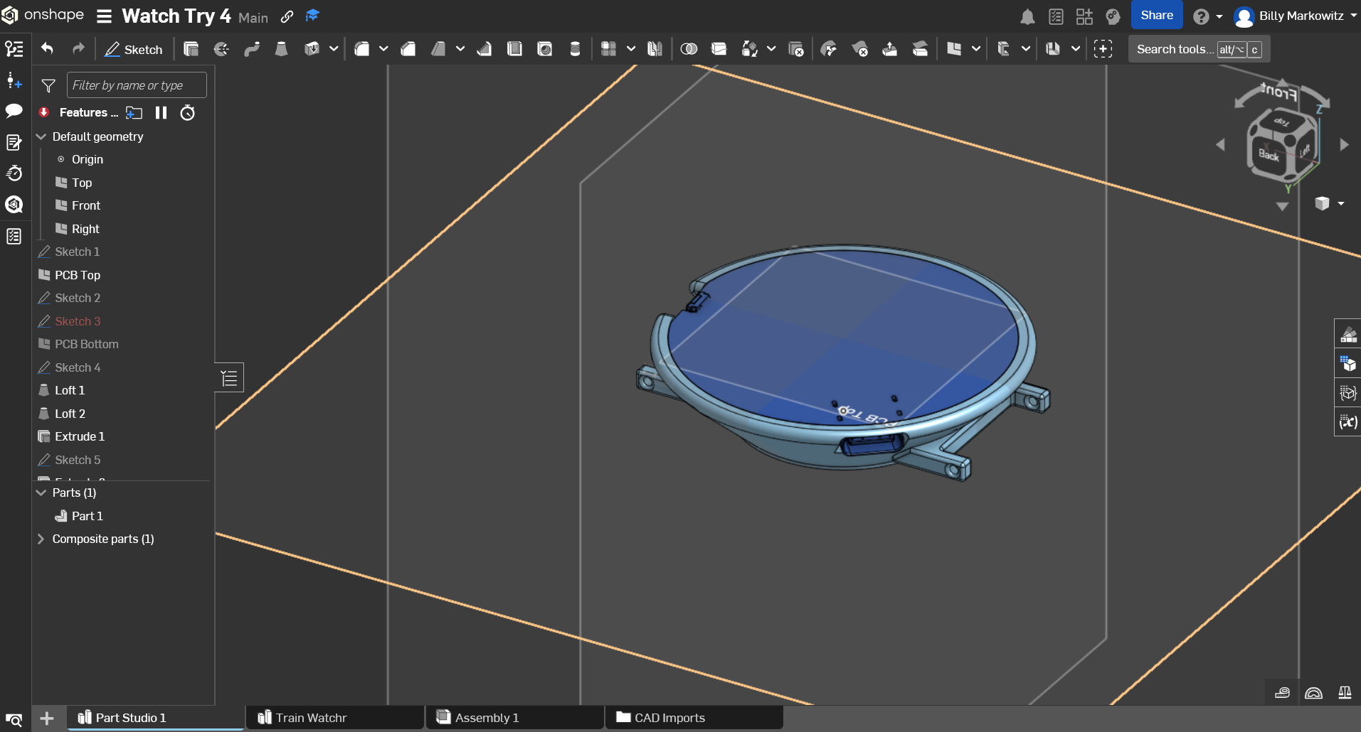
For the design of the case, I first exported a STEP file of my PCBA, which made it easy to leave cutouts for larger components, the USB port, and the button. You can see in the above image both the PCBA and the watch body. The only other major consideration in the design of the body was to make it compatible with 20mm watch bands/spring bars. This allows us to purchase generic watch bands and easily attach them to the case.
I think the watch looks awesome, but it is not without flaws. The biggest issue I have with it is that the body slopes inwards in a sort of “reverse pyramid”.
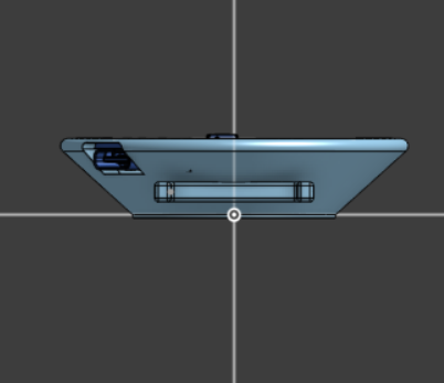
The watch face also currently sits flush with the surface. I thought this would look good (and still think that), but as a result the watch is more delicate than I wanted. I had accepted early on that the first revision of the watch would not be waterproof. But the 0201 LEDs are very delicate. I’ve noticed on the watch I wore most, that many of the blue line LEDs became damaged, I believe just from bumping against my jacket as I put it on/removed it.
Conclusion #
This project was a joy to create. People have all been very positive about it. I see many flaws that I would love to fix in another revision, but I also am proud of the quality of the final product. We never had the intention of selling these; all we wanted was to make and share a cool thing. Thank you for reading this, hopefully you enjoyed!